
-
N.CAD NCAD/ N.CAD Basic (WOP)
- Hardware Requirements
- Installation
- Moving the N.CAD Software to a New Computer
- Standard Paths
- The cc.ini
- The Default Post Processor Output Path
- Setting up a Floating Network License
- Opening NCAD or WOP
- The User Interface
- Tools and Tooling
- Machining
- Adding Comments
- Variables
- Programming
- Blocks
- Symbols
- The Safety distance (default.fmc)
- Adding Comments
- Turning on PostProcessor troubleshooting mode
- AutoRunner
- Tips
N.CAD NCAD/ N.CAD Basic (WOP)
A CAD/CAM software using a graphic UI interface to design and communicate toolpaths and machinings instructions to CNC machines.
For support documentation for N.CAD Doors, please see:
External -
https://www.eurosoftinc.com/public/documentation/doors/trac/Eurosoft/wiki/Doc/doors.html
Internal (Eurosoft, Inc. personnel) -
http://mercurial-vm/trac/Eurosoft/wiki/Doc/Doors
*N.CAD was formerly known as COBUS. In legacy images that refer to COBUS in this documentation, please substitute N.CAD in its place.
Hardware Requirements
PC with 32 or 64-bit processor from Intel Core i5, 1 GB RAM, CD- or DVD-Rom-drive, at least 2 GB free disc space on the hard disc drive, 1 USB interface, keyboard, mouse, and 17“-monitor (1280 * 1024 pixel), operating system Windows 7, 8 or Windows 10 completely installed and ready for operation. The PC shall meet the requirements which are named by Microsoft for the respective operating system. For an efficient software service and best support from our Support-Team the computer should be connected to the internet.
Installation
Installation with an Installer
Using the N.CAD installer, run the setup.exe to go through the installation process as shown below.


The software will by default install in the
C:\
directory, however any viable local directory can be selected.
A directory: C:\NCAD#### is recommended (#### = the NCAD version Year ex.: NCAD2025).

Click Yes to create the directory.

Once installation is completed, click Finish .
Installation with a ZIP File
If a ZIP file containing the full software version was provided instead of an Installer, then this can be directly installed onto the user computer. Simply extract all the files from the ZIP file into the desired location in the directory. Again, a directory in the main C:\drive, such as C:\NCAD####, is recommended (#### = the version Year ex.: NCAD2025).
Run ccCheck
When the N.CAD software has been installed, open the folder location it was installed in and find ccCheck.exe . Right-click on ccCheck.exe and select Run as Administrator .

When ccCheck opens, the populated file path in the first dialog should be the same folder location where the software is installed. Click OK .

Under the Tools option, select Installation wiederherstellen . This will install the necessary .dll files to run the software.

Once complete, close ccCheck and run NCAD.exe or NCADBASIC.exe if WOP was purchased.
Moving the N.CAD Software to a New Computer
If the N.CAD software is being moved or copied to a new computer, then the best course is to compress the entirety of the existing N.CAD version in a ZIP file. Transfer the ZIP file to the new computer and then unpack the ZIP file into the desired location in the directory. A directory such as C:\ccw#### is recommended (#### = the NCAD version Year ex.: ccw2017). Then boot the N.CAD software us usual. As long as a viable USB key, network license or temp license is also installed on the new computer, then the N.CAD software should open.
If the user has the older licensing version, they are licensed with a KLD file (or possibly temporary KLE file) and a physical dongle. The dongle will need to be moved to the new computer, and it will need to be lit up with a red light. If the dongle is not lit up, run the dongle software from here: Z:\Products\COBUS\Training and Help\additionals\Dongeltreiber .
Standard Paths
A directory in the main local drive, such as C:\NCAD####, is recommended (#### = the NCAD version Year ex.: NCAD2025) when installing the software. The standard paths below assume this install procedure was followed.

The cc.ini
The cc.ini controls many specifics of how the N.CAD software operates. It is typically located in the main NCAD directory folder (C:\NCAD####).
Most importantly the cc.ini contains the settings for where the N.CAD software looks for files such as the fmc and symbol files that control dialogs and user functionality, as well as the tool files for the tool magazine and machine set-up. Multiple versions in use at the same location can share these files by pointing to common file paths on a shared computer (a server for instance). The cc.ini is where the shared folder paths are defined.
Additionally, Machine identification, the output path for individual machine postprocessing, as well as tool optimization modes are defined here.
The Default Post Processor Output Path
By default, NCAD and WOP are set up to output machine instruction files to the corresponding machine folder in the main directory. These folders are labeled: M#. The # is for the specific machine number. Machine numbers are numbers selected for machines when the software is first setup or when additional machines are added. Usually numbering is done sequentially starting at 1. Below, an example of the numbering of machines in NCAD and the corresponding machine output folders in the main NCAD directory:

Changing the Postprocessor Output Path
Note: Changing the output path or otherwise modifying the cc.ini file should be done by advanced users only.
If a different output from the default location is desired, then that can be changed in the cc.ini.
Locate the cc.ini in the main NCAD directory and open it into a text editor such as Notepad. Scroll down until you see a row starting with [MASCHINE#] and then a row beneath that reading Bezeichnung=Machine (M#). Each block of code in this section relates to a specific machine. So in the example below, there are 3 machines used in this NCAD version; A Biesse, Weeke and Ima designated MASCHINE2, MASCHINE3, and MASCHINE5 respectively.

"FormatSrcName=" is the line of code that designates the output path. A specific hard-coded path can be designated here or a path can be specified that automatically saves the generated machine code to the same drive, directory and file name as the saved part file (the .FMC file) that the machine code was generated from. Example: FormatSrcName=%s%s%s.cix,DRV,DIR,NAM is a full automatic path assignment. This path will save the machine code to the same drive, directory and with the same file name as the original saved part file. Depending on the machine used to generate the code an additional folder designation will also be added. So if the file that the code was generated from was saved as C:\ccw2015\Example1.fmc, and the machine selected was the M2 machine, then the machine code file will be saved as C:\ccw2015\M2\Example1.cix.
Each %s tells NCAD if the drive, directory and name will be used and each %s corresponds to the drive (DRV), directory (DIR) and name (NAM).

So, as an example, if the same name as the save file (FMC) was desired but the user wanted the machine file saved to a different location (a hard coded location on the server, drive Z:\), then the previous example might be written as: FormatSrcName=Z:\MachineFileFolder\Biesse\%s.cix, ,NAM. and the file would be saved as: Z:\MachineFileFolder\Biesse\Example1.cix
Calling programs from Postprocessor
When the postprocess runs, other programs can be called. For example, when using the SCM Morbidelli output, the program creates an XXL file. When posting, an external program is called to convert the XXL file to a PRG file (the native format of SCM Morbidelli controllers). The path to the converter program needs to be set under Machine -> <desired machine> -> Configuration menu. When the configuration opens, sort by Gruppe/Group. Look for the group Nachbearbeitung, and then for field externes Programm nach_PP_Ende/External program after PP End. The Wert field above the explanation of the externes field needs to be populated with the path to the external file. In our example, the field needs to be populated to the path for the WinXIso file.
Setting up a Floating Network License
Note: Setting up a Floating Network License or modifying the cc.ini file should be done by advanced users only.
Plug the key in on the computer where the network license and shared files will be saved. We'll refer to this computer as the "Server" computer in the subsequent network installation instructions. A "repository" of all of NCAD's shared files and folders need to be saved to the Server. These include the licenses, symbols, blocks, tools etc. Most often, to avoid leaving out any important files or folders, a copy of the main local NCAD directory is simply made and placed on the Server. For our purposes, we will make a copy of the full local NCAD directory folder and place it on the Server. Make sure that all users who will utilize the network version have read/write permissions to the Server NCAD directory folder so that they can access the files and folders within.
A new network drive will need to be mapped to the NCAD directory folder that was placed on the Server. Select a drive designation that is currently not already in use and either browse to the NCAD directory Server location or input the folder location manually. In the example below the Server NCAD directory was mapped to drive N:\:

In the local NCAD directory, browse to and open the cc.ini into a text editor such as notepad. Switch all paths in the top section of the cc.ini (except the LOKALPFAD) to point to the new mapped network drive:

On the local machine, browse to ccCheck.exe in the main NCAD directory folder and open it. In the menu select "Netzlizenz" then "KLC einrichten".

In the new dialog that opens click "KLC Einrichten". A new .KLC file (a network license) will be created and saved to the mapped network drive location.
Map a new drive to the network license location on every computer where the network license will be used.
Note: The NCAD directory folder copied to the server acts as a shared "repository" of all licenses, tools, blocks, symbols, etc. that all network users will access and use. However, NCAD will still open and run locally on the user's computer and is NOT being run off of the server installation. In other words NCAD.exe or NCADBASIC.exe are still being opened locally and are not called off of the server. Therefore any .ini files (the cc.ini being the most important), which are used to set and launch program parameters, are not shared across the network and must be modified individually at each local workstation. However, updates to licenses, symbols, blocks, etc. should occur via the server files and must only be done once to update all users.
Moving the Network License to a New Location
Each time the shared network files and network license are moved to a new location, the .KLC file will need to be re-established. On the local machine, browse to ccCheck.exe in the main NCAD directory folder and open it. In the menu select "Netzlizenz" then "KLC einrichten".
In the new dialog that opens click "KLC Einrichten".
After the first install of the .KLC network license, a prompt will appear with a code. Copy and send this code to Eurosoft. Eurosoft will send a corresponding verification code from N.CAD. Once you receive the verification code paste it into the appropriate field and hit "OK" to re-establish the .KLC license file.
Opening NCAD or WOP
NCAD is launched by running NCAD.exe. WOP launches using NCADBASIC.exe. Depending on the type of version purchased, one of these will be found in the main N.CAD software install directory. If installation was done with an installer, then in many cases a N.CAD software icon will be placed on the desktop for easy accessibility. If no icon was created on the desktop or one is desired then go to the main install directory, find either NCAD.exe or NCADBASIC.exe and send a shortcut to the desktop.

The User Interface
The interfaces of NCAD and WOP are very similar.
The Top Menu
At the top of the application is the top menu bar. The customary open, save, print, and recent document functionalities can be found under the "File" menu:

Under "Edit" are the typical undo, redo, copy, cut and paste functions as well as several options for reading and saving blocks and/or symbols:

Under "Machine" are many machine specific options including posting to the machine, selecting the active machines, accessing the tool magazine and editing the tools on individual machines:

Some of these options in more detail:
- CNC generate
- One of the areas where the user can select to run the post processor/s
- Single machine selection
- Click to turn on/off. If this setting is active, then the post for only one single machine can be run at a time.
- Select a machine > Active
- Set machine as Active
- Select a machine > Edit
- Edit the tools equipped on the selected machine
Several options in the "Window" menu such as tile horizontally, arrange vertically and arrange horizontally allow different view configurations of the N.CAD software windows to be selected.

Selecting the Language
To select the desired language in which the menus dialogs, etc. should be displayed in, select Options > Settings > Select language from the top menu.

In the new dialog that opens, pick the desired language and hit OK to save.

The Tool Ribbon
The tool Ribbon includes many of the most used functions and view options. The menu can vary from version to version but almost always includes:

- 1) New file
- 2) Open
- 3) Close active file
- 4) Close all
- 5) Save
- 6) Save as
- 7) Undo
- 8) Redo
- 9) Print
- 10) Print preview
- 11) Linearize file
- 12) Post process
- 13) Zoom window
- 14) Zoom Out
- 15) Zoom in
- 16) Zoom extents
- 17) Reload symbols and blocks
- 18) Simulation
- 19) Help Directory
The Machining Ribbon
The Machining Ribbon will vary from customer to customer depending on what modules, options etc. were purchased and are installed in the N.CAD software. Modules with their own sub menus will be displayed in the "Overview" section. All versions will include machining tools. These are found in the "Universal" section.

The section in Red is the Universal Menu. When clicked, all of the machining tools become available. The items outlined in blue in the image above are modules, with their own submenus, specific to each version. When clicked, the item outlined in green with the ">>>", will display more modules.
Below is a typical layout of the Machining tools in the Universal section. Displayed is milling with all the available milling tools:

These might vary from version to version to some degree but will almost always include the sub sections: Milling, Drilling, Cycles (pockets and sawing), Contour, Machine, Set-up, Program, and User. Each of these sections, when selected, will display the tools available for the machining function. "User" is intended for use as a menu section that every user can customize to place their own most used or important tools.
"Overview" returns to the previous ribbon view including installed modules.
The Graphic Windows
Below are the typical windows that make up the NCAD graphical display:

- 1) CAD Drawing Tools
- 2) CAM Operation List
- 3) CAD Geometry List
- 4) CAD/CAM Display Window
- 5) Tool tips and location guide
In A WOP version, only CAM operations are available. Therefore the CAD drawing tools and CAD geometry list are not displayed in the WOP envionment. The WOP graphical display windows below:

CAD Drawing Tools (NCAD only)

- 1) Cancel CAD operation
- 2) Cancel CAD operation
- 3) Line through 2 points
- 4) Extend line
- 5) Rectangle (diagonal points)
- 6) Explode rectangle
- 7) Circle (center + point)
- 8) Circle (center + radius)
- 9) Arc (center + 2 points)
- 10) Arc (center + radius + angle)
- 11) Point (XY)
- 12)
- 13) Intersection point (breaks all elements down)
- 14) Point next to line
- 15) Parallel path
- 16) Rounding 2 elements
- 17) Contour rounding
- 18) Chamfer 2 elements
- 19) contour chamfering
- 20) Drawing frame
- 21) Intersection point (breaks 1st element down, trims 2nd element)
- 22) Intersection point (trims both elements)
- 23)
- 24) Line sub-menu
- 25) Circle and Arc sub-menu
- 26) Manipulate sub-menu
- 27) Dimensions and text sub-menu
- 28) Contour sub-menu
- 29)
- 30)
Line Sub-menu

- 1) Return to main menu
- 2) Cancel CAD operation
- 3) Rectangle (center + corner point)
- 4) Rectangle (diagonal points)
- 5) Rotated Rectangle
- 6) Explode rectangle
- 7) Line through 2 points
- 8) Extend line
- 9) Line parallel to line at a distance
- 10) Line parallel to line through point
- 11) Line perpendicular to line at a distance/length
- 12) Line perpendicular to a line through a point
- 13) Tangent from point to circle/arc
- 14) Tangent on 2 circles/arcs
- 15) Perpendicular from circle onto line
- 16) Line parallel to line tangent on circle
- 17) Regular polygon (center + corner point)
- 18) Regular polygon (diagonal points)
- 19) Zigzag line
- 20) Intersection point (breaks 1st element down, trims 2nd element)
- 21) Intersection point (trims both elements)
- 22)
- 23) Return to main menu
- 24) Circle and Arc sub-menu
- 25) Manipulate sub-menu
- 26) Dimensions and text sub-menu
- 27) Contour sub-menu
- 28)
- 29)
Circle and Arc Sub-menu

- 1) Return to main menu
- 2) Cancel CAD operation
- 3) Circle (center + point)
- 4) Circle (center + radius)
- 5) Circle (2 Diameter points)
- 6) Circle (3 points)
- 7) Circle (2 points + radius)
- 8) Circle (tangent + center)
- 9) Circle (tangent + 2 points)
- 10) Circle (tangent + radius + point)
- 11) Circle (2 tangents + point)
- 12) Circle (2 tangents + radius)
- 13) Circle (3 tangents)
- 14) Arc (center + 2 points)
- 15) Arc(center + radius + angle)
- 16) Arc (3 points)
- 17) Arc (2 points + radius)
- 18) Rounding 2 elements
- 19) Contour rounding
- 20) Ellipse (center point + radii)
- 21) Ellipse in rectangle
- 22) Intersection point (breaks 1st element down, trims 2nd element)
- 23) Intersection point (trims both elements)
- 24)
- 25) Return to main menu
- 26) Circle and Arc sub-menu
- 27) Manipulate sub-menu
- 28) Dimensions and text sub-menu
- 29) Contour sub-menu
- 30)
- 31)
Manipulate Sub-menu

- 1) Return to main menu
- 2) Cancel CAD operation
- 3) Move (from > to)
- 4) Move (by)
- 5) Scale (center + factor)
- 6) Rotation (center + angle)
- 7) Mirror (across X)
- 8) Mirror (across Y)
- 9) Mirror
- 10) Point offset
- 11) Mark via window
- 12) Copy marked elements
- 13) mark 1 element
- 14) Unmark 1 element
- 15) Mark all
- 16) Unmark all
- 17) Delete marked elements
- 18) Convert marked elements to contour
- 19) Define a closed contour
- 20) Color
- 21) Background color
- 22) Line type
- 23) Line thickness
- 24) Fill pattern
- 25) layer
- 26)
- 27)
- 28) Line sub-menu
- 29) Circle and Arc sub-menu
- 30) Return to main menu
- 31) Dimensions and text sub-menu
- 32) Contour sub-menu
- 33)
- 34)
- 35) Convert circle to drill hole
- 36) Convert drill hole to circle
Contour Sub-menu
The CAM Entry List
Active Row and Sequence
Displays a sequential list of all CAM operations and associated programming. Listed here will be all actions that define the manufacturing operations to be carried out on the part, design, etc. The row highlighted in blue is the current active row. A new operation will be inserted previous (above) to the current active row. The order of operations in the CAM list is important. The N.CAD software processes through the operations in the list from top to bottom. Therefore if any operation is dependent on another operation occurring previously, then the dependent operation must be placed after the primary operation in the CAM list in order for it to work correctly. Additionally, if the tool optimization module is not part of the version, then tool sequencing in the post occurs in the sequence that entries are defined in the CAM entry list.
One very simple example illustrating this is if a machining operation is added before the workpiece is added. In the CAM list, the machining operation occurs before the workpiece. In the image below, a trim cut (formatting) was added before the workpiece:

We see the workpiece but the trim cut is not displayed. This is only natural because the trim cut requires the dimensions of the workpiece to calculate out how it will function properly. Because the N.CAD sofware processes the operations in the CAM list from top to bottom, the dimensions of the workpiece cannot be passed up to the trim cut.
If the Trim cut is moved below the workpiece, it is now able to function as expected:

Blocks and Symbols in the CAM List
Blocks and Symbols can typically be recognized in the CAM list by the green plus mark next to the operation item:

By clicking on the green plus mark, the block or symbol will expand. Contained within are all the operations and programming process used to define the block or symbol. Below, the Formatting symbol has been expanded.

Notice that on row 4 of this example, the symbol is officially called and the folder location where the block (blk .fmc file) of operations is saved in the directory, is identified. Similarly, row 23 is where the symbol concludes.
Active and Inactive Rows
The above image is also a good example to point out the red and green dots to the left of the CAM list row numbers. All rows have a green dot next to them except for row 6 which has a red dot. The dots represent if the operation is being executed or not, green for active and red for inactive. In this case the variable defined on row 6 is not being executed because the condition on row 5 is not being met. Instead it skips on to the elsif condition on line 7 which is being met and executes the block of code associated with that.
The CAD Geometry List
Displays a sequential list of all CAD elements in the part file. This can include any type of 2D geometry, text, hatching, etc. used only for graphical representation and not associated with manufacturing objects or operations.

Functionality in the CAD List is similar to that in the CAM List. See CAM List for utilization information.
The CAD/CAM Display Window
The CAD/CAM Windows graphically displays the CAD and CAM elements that were added to the part file. The CAD/CAM window will remain blank until some operation or feature has been added. Below the workpiece has been added:

In many cases how items are displayed in the CAD/CAM window can be modified. As an example, below the graphical representation of the Workpiece in the CAD/CAM window can be modified in the Workpiece symbol dialog itself:

Tools and Tooling
In order for the N.CAD software to post process correctly, tools need to be added to both a repository of tools called the "Tool Magazine" and associated (equipped) on the individual machines according to their intended function.
Setting up Tools
To set up tools in the N.CAD Software, select machine from the top menu bar, then tool magazine . The Tool magazine is the tool repository. ALL tools need to be created here, regardless of what machine they are equipped on in actuality.
Typically NCAD and WOP versions come with several tools pre-loaded. These will load on the left in the CAM list and can be modified to accurately represent tools on-site, used as examples on how to create new tools or simple deleted to remove clutter.

A list of tools in the tool magazine after loading:

To access a tool's parameters either double click on the tool in the tool menu to the left or right click on the tool and select "edit" from the pulldown menu that appears:

To add a new tool, select the tool type from the top three icons:

 is for drilling tools.
 is for milling tools.
 is for sawing tools.
Select the appropriate tool type. The tool properties window will open where the user can enter the tool's values.

Most of the relevant values are accessible from the page 1 tab.
- tool-ID
- The name of the tool within NCAD. This is not the same as the T-number of the machine.
- radius
- The tool's radius.
- length
- The total length of the tool.
- H-number
- Tool length offset. This value should match the value set in the machine's controller software.
- Usable length
- Length of the tool that the machine can use for drilling, milling, or sawing operations. Should be equivalent or less than the total length of the tool.
- rotation direction
- Direction in which the tool will rotate.
- 1st drilling feedrate
- drilling feedrate
- Feedrate while drilling.
- feedrate min
- Minimum feedrate.
- feedrate max
- Maximum feedrate.
- rest drilling-feed
- default rotational speed
- cover position
- Hood position.
- Bohrertyp
- Drill type.
Once the tool values have been entered, click OK to exit the configuration dialog window.
When all tools have been entered, save the tool magazine by clicking the "Save" button or go to File > Save
Machine Set-up
The 2nd part of tooling in the N.CAD software is to assign the tools to their respective machines. This is done individually per machine. To open the machine set-up for a machine, select machine from the top menu bar. The drop-down list will show the machines the installed N.CAD software version has been licensed for. Mouse over the machine to the sub-list and select the edit option. This will open the settings for the selected machine where the tooling equipment (tool changer, aggregates etc.) can be set-up and also where tools can be linked.

In the CAD/CAM window is a visual representation of the tooling equipment of the specific machine. To the left in the CAM list are the symbols that create the tool equipment representation and functionality, as well as a list of all equipped tools.
Although it is advisable to set up as accurate a reflection of the tool changers, drill heads, aggregates etc. as they are on the actual CNC here in the NCAD Machine Setup, it is not necessary to recreate this to 100% accuracy. Equipping a tool to a machine is for the purpose of the N.CAD software to know what tools can be used at which machines, how those tools can be used (vertical, horizontal machining, etc.) and to pass tool identification to the actual machine or machine controller software for proper tool selection via the post processor.
Tooling Equipment Representations
There are numerous ways in which the tooling equipment can be represented in the N.CAD software however, for instructional purposes we will assume that the tooling equipment on the machine consists of:
1) A tool changer represented by a circle with a specific amount of numbered tool slot locations
2) A drillhead block represented by a rectangle with a number of drill bit slots
3) Horizontal aggregates represented by a number of chuck heads

In addition to these visual equipment representations there is typically an extraneous tool storage bin represented by a purple rectangle:

Tools that are in this storage bin will still be called in the post processor when the corresponding machine post processor is run, however, typically if a tool is in this storage bin it means that the tool was not equipped on the tooling equipment correctly in the N.CAD software. For instance, if 2 tools are placed on the same slot on the tool changer, the 2nd tool assigned to the slot will appear in the storage bin because the slot where it was assigned already has a tool in it. Best practice is to rectify issues with tools in the storage bin and keep the bin empty.
Modifying Existing Tooling Equipment
Note: The tooling equipment should be modified by advanced users only. Improperly configuring the tooling equipment can lead to the post processor not functioning properly.
To edit any of the tool equipment components, expand the machine selection symbol (TOMMASCH). The individual tooling equipment components are listed within. In the example below, the expanded machine selection and corresponding block are on lines 1 and 2, the tool changer is on row 5, followed by the drill block and then 4 rows for the 10 horizontal aggregates. A fixed aggregate is on line 11:

Typically all tooling equipment in the N.CAD software needs to be assigned an aggregate number and/or the numbering sequence for tool slots. Some machines or manufacturers base the tooling identification on the position of the tool in the tool changer etc. If this is the case, then it is important to set up the aggregate numbers and position slot sequence correctly in the N.CAD software, in order for the correct position number to be output in the post processor. If the tool position is not important for tool identification, it is still a good idea to set these up in a logical fashion in the N.CAD software for organizational purposes.
The Tool Changer
Double click on the tool changer ("plate changer") entry in the CAM list to open the tool changer settings dialog.

Some more details on some of the settings in this dialog:
"General tool data" tab:
- Tool Identifier
- Unique ID for the changer
- 1st position number
- The start of the tool slot position numbering
- Number of places
- How many tool slots are on the changer. In conjunction with the 1st position number value, the tool slot numbering sequence will begin at the value specified in the 1st position number and continue sequentially from there according to how many tools slot places are specified here. Changing the value here will automatically change the number of slots in the graphic representation of the tool changer in the CAD/CAM window.
- Aggregate number
- A unique number assigned to tooling equipment for identification during tool placement
"Graphical representation" tab :
- Center point X and center point Y
- Where in the CAD/CAM display the tool changer will be placed. For visual clarity the tool equipment should be arranged so that they do not overlap. To a lesser degree, the positioning should represent the true nature of the equipment on the machine itself, however, a 100% accurate representation is not necessary.
The Drill Block
Double click on the Drill Block (called Lochreihe by default) entry in the CAM list to open the drill block settings dialog.
Some more details on some of the settings in this dialog:
- Tool Identifier
- Unique ID for the Drill Block
- 1st spindle T number
- The start of the tool slot position numbering
- X and Y offset
- Where in the CAD/CAM display the drill block will be placed
- Number of spindles
- How many tool slot positions are in the drill block. Changing the value here will NOT automatically change the number of slots in the graphic representation of the Drill block in the CAD/CAM window. To add more position slots,
a new spindle has to be manually added, by expanding the drill block symbol and adding a new spindle manually. This can be done by calling the single spindle symbol (setspindelinbohrbalken) or by copying and pasting an existing spindle and editing the new spindle information with position and spindle number
- Aggregate number
- A unique number assigned to tooling equipment for identification during tool placement
Horizontal Aggregates (4 axis machining, appropriate post required)
Double click on the Horizontal Drilling beam entry in the CAM list to open the Horizontal Aggregate settings dialog.
In general the settings of the Horizontal Drilling beam are similar to the Drill block.

More important here are the rotation settings of the aggregates. For fixed aggregates the fixed rotation direction must be specified to insure the drills bits equipped are able to drill in the appropriate direction. This is set in the rotation angle min and max on the 2nd tab. A value of 0 in both the min and max rotation angle will fix the aggregate to point right in the X+ direction. 90 = Y+, 180 = X-, 270 = Y- direction. If a different rotation minimum and maximum is entered into the fields then it is assumed that the aggregate is not fixed on the machine but can rotate. For instance, if a rotation min of 0 is selected and a maximum of 270, then in theory, the aggregate on the machine can rotate in all directions and separate fixed horizontal aggregates may not be needed.

Adding a Horizontal Aggregate
On the machining menu, switch to the "machine" tab and select the "mount horizontal spindle" tool:

In the dialog that opens, first assign a name in the "tool-identifier" field. Pick a number for the T-Number 1st spindle which will define the tool slot position numbers for this aggregate. 1 is typical.
To position the horizontal aggregate graphically in the CAD/CAM window adjust the value in the X-offset and Y-offset fields. Set the number of spindles required for this aggregate in the "number of spindles" field. Most importantly, select an aggregate number that is not being used by any other aggregate already in the machine set-up.
On the 2nd tab input the rotation angle min and max to specify in what direction the aggregate is positioned or a range if the aggregate can rotate.
Here an example for a horizontal aggregate with the drill active in the Y+ direction:

...and the resulting graphic representation (with tool equipped)

Using the same process as above for 3 additional horizontal drill aggregates to create a representation of a fixed drill aggregate head with 4 drill spindles mounted at 90degree increments:

Note the 4 unique aggregate numbers, 1 for each horizontal drill aggregate created, so that the drill bits could be assigned to the correct aggregate and position.
Assigning Tools to the Tooling Equipment
To assign a tool, click one of the three icons located to indicate the tool type (drill, mill, or saw). Note that the tooltip will now say either "select" drill, milling tool, or saw.
If the cursor changes to a cross-hair then the tool can be placed via mouse click into an open slot on the tool changer, drill head, etc. Simply move the mouse over to an open slot position, typically represented by a green plus sign with a number next to it...

...and click to place the tool there:

A dialog will open displaying the tool placement options. Some more details on some of the settings in this dialog:
"page1" tab :
- Tool Definition
- Select the tool to place
- Position number
- The tool slot position on the desired tool changer, drill block or aggregate
- D-number
- Optional. The D parameter
- H-number
- Optional. Used by some machine controller softwares for the length offset of the tool
- Aggregate number
- The unique number assigned to the desired tool changer, drill block or aggregate
"page1" tab :
- T-number
- The tool number. Used to match the tool in NCAD with the tool on the machine as designated in the machine controller software
The N.CAD software will fill in some information, such as the Position and Aggregate Numbers, automatically according to what was selected by the user when placing the tool.
If mouse selection is not available for placing tools, then the tool must be placed manually via the placement dialog. In this case, after selecting what type of tool to place, the cursor will not switch to the cross hair placement mode, instead the placement dialog will immediately open. First select the changer, drill block or aggregate by typing in the appropriate aggregate number. Next add the position number of where on the specific aggregate the tool should be placed. .
Make sure to save any changes to the machine tool configuration by clicking the "Save" button or going to File > Save.
Setting the T-number
The T-Number is the number designated on the machine for the specific tool. In the end, this is what NCAD uses to call the correct tool in the post and tie it to the machine. In the shown example, it is set to the WKZP variable, which is also the variable for position number from the page 1 tab. Some machines use the position of the tool in the changer as the tool identifier and that is what using WKZP would accomplish if the tool changer is set up in NCAD to match the machine. However, this can be changed to any hard-coded number that identifies the tool.

Repeat the same process for any other tools that need to be assigned. When postprocessing a job to a machine, the T-number will be passed to the controller and as long as the machine controller knows the actual location of the required tool, it will pick the correct one.
Save the machine tool configuration by clicking the "Save" button or going to File > Save.
Machining
Drilling
In the machining Ribbon, select the "drilling" tab to open the drilling tools.
Adding a Single Hole
In the "drilling" tab select "vertical drilling":

Click on the part to place the drill hole according to mouse location. The drill hole dialog will open where the position along with other options can be modified:

Some more details on some of the settings in this dialog:
- Diameter
- Enter the diameter of the hole. This value is ignored if a specific tool is selected in "page 2".
- Depth
- Enter the depth that the tool should reach. Starting reference level is the surface of the workpiece.
- Safety distance
- Indicates the safety distance for this single drill. The default value , "SAZ", is defined in the Default.fmc.

- Tool-id
- Default = "auto". If "auto" is used then the diameter on "page 1" will be used to select a tool from the tool magazine with a matching diameter. If no matching diameter tool is found then in all likelihood errors will be recorded in the Postprocessor. If a specific tool is desired then select it from the pulldown menu. This assignment will supersede that of the diameter on "page 1".
Adding a Multi Hole Pattern
Multi Hole Patterns will place multiple drill holes to a maximum of 8. If a parametric solution using more than 8 drill holes is required, for instance for line boring, then please see "Adding a row of drill holes". Select "vertical drilling pattern in X" (or "vertical drilling pattern in Y") from the drilling menu:

Click on the part to place the start position of the hole pattern according to mouse location. The Hole pattern dialog will open:

Some more details on some of the settings in this dialog:
- Drilling Position X1/Y1
- Define the position in X and Y of the first drill hole.
- Incremental measure in X
- Defines whether the subsequent drill holes are positioned incrementally as chain dimension distances from each other, or whether these coordinates are to be placed at absolute distances from the first drill hole.
- Drilling Position X2-X8
- Define the distances to drill holes 2 through 8.
- Drilling position Y 2row
- Defines the Y-position for a second row of drill holes parallel to the first. The value for the Y-position has to be greater than the Y-position of the first row.
For info on "Page 2" see section Adding a single hole here
Adding a Row of Drill Holes
Drill locations using the row of hole tools are calculated automatically based upon the data provided in the tool dialogs. For instance, a common example is providing a start, endpoint and spacing interval. Using this information, NCAD will calculate out and place the drill holes accordingly. Select "Row of holes in X" (or "Row of holes in Y") from the drilling menu:

Click on the part in the design window to indicate the start position for the row of holes. The Row of holes dialog box will open:

The settings explained:
- Start point X
- Defines the start point in X of the line on which the row of holes is placed. Note that this does not necessarily mean that the first drill hole will occur at that point. This also depends on the "spacing" setting. See below.
- End point X
- Defines the final point in X of the line on which the row of holes is placed. Note that this does not necessarily mean that the last drill hole will occur exactly at that point. This also depends on the "spacing" setting.
- Y-position row 1
- The position in Y of the row of drill holes
- Y-position row 2
- The position in Y of a 2nd, optional row of drill holes parallel to the first. The value for the Y-position has to be greater than the Y-position of the first row.
- Spacing
- Defines the distance between the drill holes
- Center
- Determines how an unequal distance (the sum of the spacing distances is not equal to the distance between start and end point) is handled: Selecting SPX places the first drilling on the "Start point X"; EPX places the last drilling on the "End point X".
For info on "Page 2" see section Adding a single hole here
Horizontal Drilling
Adding a Single Hole
In the "drilling" tab select "horizontal drilling":

Position the mouse along the edge of the part where the horizontal drilling is needed and click to place. The Horizontal Drilling Dialog will open:

Some more details on some of the settings in this dialog:
- Drilling Position Z
- Indicates the starting point in Z of the drill hole. By default, half the workpiece thickness (S/2) is used.
- Drilling Angle XY
- The angle of the drill hole, starting at 0 on the X-axis and rotating counterclockwise. "auto" = perpendicular to the workpiece's edge if an edge was selected when originally placing the horizontal drilling.
- Safety distance X
- Defines the horizontal safety distance from the workpiece edge. The default value , "SAZ", is defined in the Default.fmc.
- Safety level Z
- Defines the vertical safety distance from the workpiece surface. The default value , "SAZ", is defined in the Default.fmc.
For info on "Page 2" see section Adding a single hole here
Milling
Milling can be done in 2 ways: Manually or with contours.
Manual milling
Open a new file and add a workpiece with the desired dimensions.
On the Milling toolbar select the "Contour approach" icon.

In the dialog that opens, select the desired tool and approach settings to be used for this operation. If variables are not being used, insert the exact start location into the X and Y coordinates.

Hit "OK" to close the dialog and place the approach.
The path of the milling operation can be defined using the following geometries: Straight Line, Arc Clockwise, Arc Counterclockwise and Tangential.

Using these geometries, describe the path of the milling operation. Below is an example, having placed 2 lines:

Each milling geometry begins at the termination of the geometry that preceded it. So having the geometries in the correct sequence in the CAM list is important. Below are the results of 2 identical milling operations, with the exception that the highlighted "Straight Line" geometry is in a different sequence in the CAM list.

When all geometries have been added and the milling path is complete, the path must be terminated by adding the departure. Select "Departure" from the menu.

In the Departure Dialog, settings left as "Auto" will use the same settings as those selected in the Approach. If other settings are desired, select them from the appropriate pull down menu.

Hit "OK" to close the dialog, place the Departure and terminate the milling path.
Manual contour milling
Manually determining the path of a milling operation via contours is very similar to manually adding milling directly. The difference between manually adding milling directly and manually adding milling via contours is that contours can be defined and named. This allows them to be called and manipulated in subsequent or concatenating operations and overall, allows for a greater range of functionality.
The toolbar items for adding manual contours are very similar to those used in manual milling. They consist of the Start Contour, Contour Line, Contour arc clockwise, contour arc counterclockwise and End Contour.

To begin, select the "Start Contour" Icon. In the dialog that opens enter the X and Y coordinates. This start position determines the approach position of the tool. Similarly when the End Contour is placed, the End Contour will determine the departure position of the tool.
Enter a name for the contour. This is the contour's designation and will be what is called when the contour is referenced in subsequent operations involving the contour.

Use the Contour Line, Contour arc clockwise, contour arc counterclockwise geometries to define the path of the contour. When the path is defined as desired, complete and close the contour by adding the End Contour.
Let's look at a simple but complete contour example below:

Notice in the CAM list the lines marked as the start and end contour. Everything between these 2 CAM lines will be designated as part of that contour. Next to the start contour and in the drawing itself, the name of the contour ( ExampleContour? in this case) is displayed for easy identification of the contour.
Assigning a contour to CAD Elements (NCAD only)
Contours can be assigned to CAD elements in the drawing field. CAD elements can be drawn manually or imported from other file formats such as DXF. The CAD elements by themselves cannot be machined. They are simply 2D geometries. Instead contours have to be assigned to CAD shapes that represent milling elements and circular elements that represent drill holes have to assigned as such. Below is a more complicated CAD shape that can be created manually but is far easier to make using the many available CAD functions in N.CAD NCAD:

To machine the CAD elements in this example, made up of 5 arcs, they must be assigned to a contour.
To begin, select the "Manipulate" sub-menu:

In the manipulate sub-menu are several options for selecting CAD elements:

Use "mark all elements in window", "mark one element" or "mark all elements" to select the CAD items that will be part of the contour. When a CAD element has been "marked" by default it will be represented by a purple dashed line:

Once all CAD elements have been marked, click "Mark defined elements as contour path"
 to assign the selected CAD items to a contour.
By default the first contour made in this way is given a name of "_K1". Any subsequent contours made in a similar way will be numbered sequentially as _K#. If a different name is desired double click on the "start contour definition" to open the contour dialog and options. In the "name" field change the name to whatever name is desired for the contour.
Below is the previous example. The CAD elements were assigned a default contour name of _K2 (the 2nd contour made in this example). Notice in the CAD window the 5 CAD arc elements are enclosed by the "start contour" and "end contour" command lines to designate the beginning and end of the contour definition and what items are contained therein.

Milling a Contour
Once a contour has been defined the desired milling functionality must be assigned to the contour. These include the tool to be used, tool compensation (if any), lead in/out settings and multiple other options. To assign a milling operation to a contour click the "Contour Milling" Icon on in the contour menu.

In the new dialog box that opens fill out the setting as required for the milling operation. Some more details on some of the settings in this dialog:
- contour name
- Enter the name of the contour here. All settings in this dialog will be applied to the specified contour.
- In defined direction
- Counterclockwise vs clockwise rotation. Checked is clockwise rotation.
- machining level in Z
- Depth of machining. Typically (depends on machine), a negative number indicates machining that is deeper than the workpiece (a through cut). A positive value is internal to the workpiece measured from the bottom of the workpiece going up.
- radius offset
- Defines and offset (shift) between the contour geometry and the actual machining path. A positive value is a shift to left or outside, negative to the right or inside.
- corner rounding
- Input a radius to round or chamfer the corners of the contour. 0 = square corners, positive = rounded corners, negative = chamfer.
- step
- Defines whether the move to the Z-value (defined in the field "Machining level in Z") takes place before, by (simultaneously) or after the approach procedure.
Manipulating a contour
Unlike manual milling, a defined contour can be modified in a number of ways after the original path or shape is defined. Many of the contour modification tools can be found on the contour toolbar under the manipulations menu (A) or in the supplementary menus (B).

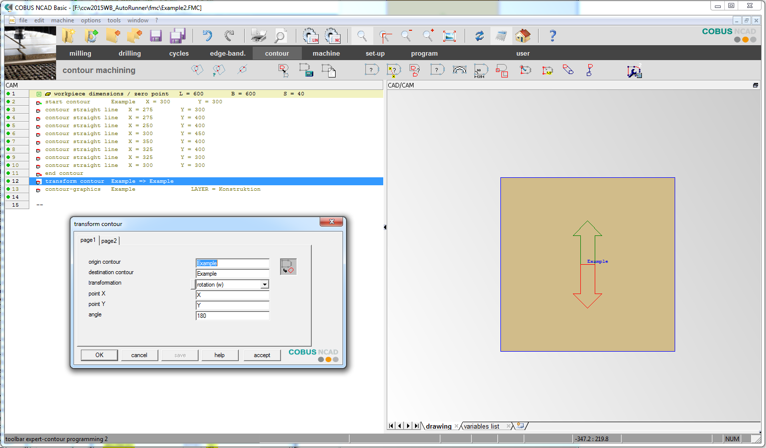
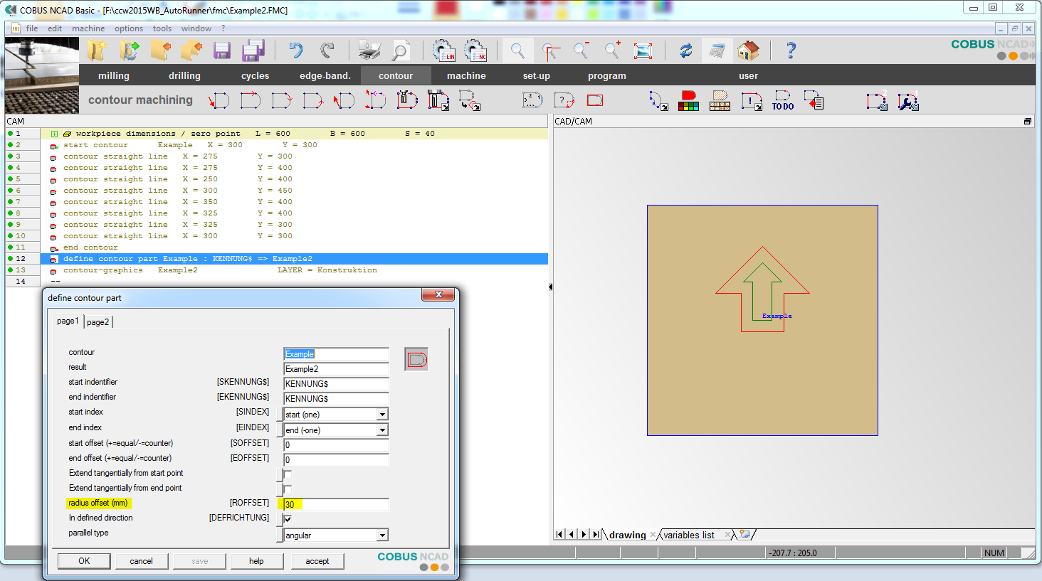
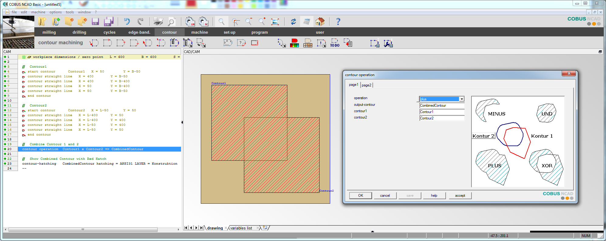
Below just a few examples of contour manipulations that can be performed (Green is the original contour, red the final contour):
- Rotate a Contour
-

- Offset a Contour
-

- Combining Contours
-

Cycles (Pockets)
In the machining Ribbon, select the "cycles" tab to access the pocket and saw tools.
Adding a Rectangular Pocket
In the "cycles" tab select "rectangular pocket":

Click on a location in the drawing field to place the center point of the rectangular pocket. The rectangular pocket dialog will open:

The settings explained:
- Tool-ID
- Select the desired tool from the pulldown menu for milling the pocket.
- Center X
- The center in X of the pocket.
- Center Y
- The center in Y of the pocket.
- Broaching
- Clean out pocket Yes/No.
- Corner radius
- If a radius is indicated here, then the corners of the pocket are rounded with this radius. A value of "WKZR" indicates the radius of the tool selected.
- Step XY
- Defines the tool overlap for cleaning out the pocket. A common overlap is 4/5 of the tool diameter (or WKZR*1.6).
- Step Z
- Defines tool movement in Z direction. For instance, if depth (TI) is 15mm and Step Z (ZUSTZ) is 5mm, then 3 passes will be needed, each going 5 mm deeper than the previous until the final depth of 15mm is reached.
- Survey XY
- Defines an offset in XY from the defined dimensions of the pocket. A positive value results in a smaller pocket, a negative value in an oversized pocket. Most common use is starting with an undersized pocket as a rough cut.
- Survey Z
- Defines an offset in Z from the defined depth of the pocket.
Adding a Circular Pocket
In the "cycles" tab select "rectangular pocket":

Click on a location in the drawing field to place the center point of the circular pocket. The circular pocket dialog will open. For more info in the circular pocket settings please see section Adding a Rectangular Pocket here . The setting between circular and rectangular pockets are all the same except for the dimensions which for the circular pocket are determined by a center point and radius.
Creating a Pocket from a Contour
A contour can be used for pocketing as well as for milling
In the "cycles" tab select either "parallel-recess" or "recess milling":

Both of these tools can be used to mill pockets out of contours. The main difference is the movement of the tool as it mills the pocket. Parallel-recess moves from the outside/in or the inside/out in parallel movements. Recess milling zig-zags back and forth moving in 1 direction.
Once either "parallel-recess" or "recess milling" is selected the corresponding dialog box will open. Below is the dialog and an example using a parallel-recess pocket:

The settings explained:
- Tool-ID
- Select the desired tool that will be used for milling the pocket from the pulldown.
- Name
- Input the ID (name) of the contour that will be pocketed.
- Reference level Z
- Defines the position in Z where routing of the pocket begins. In most cases this is the surface of the workpiece.
- Step XY
- Defines the tool overlap for cleaning out the pocket. A common overlap is 4/5 of the tool diameter (or WKZR*1.6).
- Edge finishing
-
Defines if and when a finish cut takes place to clean out the edge of the pocket. Whereas the inside milling of the pocket is done without compensation, for the finish cut a compensation is used.
-
No
- No finish
-
Last
- Finish cut is applied after the pocket is cleaned
-
No
- Step Z
- Defines tool movement in Z direction. For instance, if depth (TI) is 15mm and Step Z (ZUSTZ) is 5mm, then 3 passes will be needed, each going 5 mm deeper than the previous until the final depth of 15mm is reached.
- Survey XY
- Defines an offset in XY from the defined dimensions of the pocket. A positive value results in a smaller pocket, a negative value in an oversized pocket. Most common use is starting with an undersized pocket as a rough cut.
- Ground finishing
- If active the pocket is cleared in Z until the final Step in Z is reached. The remaining material in Z is then cleaned out by the finish cut. Generally results in a higher quality cut.
- Survey Z
- Defines an offset in Z from the defined depth of the pocket.
- Finishing with conventional cut
- Clockwise or counterclockwise rotation.
Sawing
Saw cuts are found on the "Cycles" tab. There are typically 3 tools here for sawing:

1) Formatting saw (part trim cut with saw), 2) Dado 3) Blind dado
For a simple horizontal saw cut, perhaps for the groove that a deck or top slides into, select the dado tool from the menu. Once activated the cursor will change to a crosshair for mouse click selection in the CAD/CAM window. Click to place the start of the dado cut, drag the mouse to designate the path the dado will run along and finally click again to select the end point. If specific selection points (such as corner or midpoints) cannot be selected then place the start point, path and end point as close to the desired location as possible. The location and saw settings can be fine tuned in the dialog that opens after placing the end point. Here an example after selecting start point, path and endpoint via mouse click in space:

The dialog settings explained:
- Tool-ID
- Select the desired tool that will be used for milling the pocket from the pulldown.
- Start point X and Y
- Defines the start position of the dado in X and Y
- Endpoint X and Y
- Defines the end position of the dado in X and Y
- Groove Length
- Defines the length of the groove. Any entry here will override the endpoint X and Y values
- Rotation Angle
- Rotation angle of the dado. Only applies if the value in Groove Length is greater than 0
- Groove Width
- Width of the dado. Typically determined by the thickness of the saw or tool used, however any value greater than 0 can be entered, although a value less than the tool thickness does not make much sense. If the value is greater than the tool thickness then the tool will automatically run multiple passes to complete the dado to full width
- Groove Depth
- Depth of the dado from the surface into the material
Resulting dado with multiple passes to reach full dado width:

Machining on Other Faces
By default the N.CAD software assumes that machining will be done on the top face of the part as is typical for most CNC machines and applications. If machining is required on other faces, then the face on which the machining is applied can be changed on the fly in the N.CAD software.
In the example below, a pocket needs to be placed on the left face of the part to create the lock pocket on a small door. To establish that machining should be placed on the left side of the part, the sector selection tool needs to be used. The sector selection tool is loaded by fuenfs symbol and can be found by default in the milling menu:

In the dialog that opens the most important information is the area field:

0 = default top face (Z+), 1 = left face (X-), 2 = upper face (Y+), 3 = right face (X+), 4 = lower face (Y-) and 5 = bottom face (Z-)
For the lock pocket example, to place the pocket on the left face, the radio button for 1 (X-) needs to be selected. In the CAM list a sector selection entry is made:

Once placed, the sector selection entry effects all machining that follows in the CAM list. In this case, all machining that is added after the sector selection will be placed on the left face of the part. Once all machining needed on the left face has been placed, and to return to default functionality and place machining on the top face again, another sector selection entry must be made with the area set back to 0 (Z+).
Below the completed example. The trim cut is done from the top face on row 3, then the sector selection entry on row 4 switches the active face to the left face. The entries on row 5-10 define the contour followed by the machining operation on line 11 that creates the pocket geometry out of that contour. On row 12 the sector selector entry switches the active face back to the top face.

Adding Comments
Comment entries can be made in the CAM and CAD areas and are generally used for organizational purposes. They are represented by green text preceded by 2 forward slashes.
In the example below comments are used on lines 14, 18, 23, 28 and 39 in order to explain what operations the subsequent lines are performing:

Comments are loaded by the wkomment symbol, which can typically be found in the milling menu:

In the dialog that opens, type the comment text into the field and hit OK to add the comment to the CAD or CAM list.
Variables
Variables in NCAD are the same as variables used in computer programming. A variable is a symbolic name associated with a value and whose associated value may be changed. In NCAD, variables can be used in any number of operations related to controlling the part or machining.
Internal Variables
NCAD has a large set of internal variables which are related to the Symbols (Macros) that perform the standard functionality of creating parts, adding machining, etc. The input fields (or buttons, pulldown lists, etc.) in Symbols are almost always tied to a variable. These variables are designated in the symbol dialog, next to the associated field, in square brackets. Below is the "Workpiece" dialog, one of the most common Symbols used in NCAD, with the internal variables highlighted in red:

These internal variables can be called, in place of an actual value, in subsequent operations.
In the example below, the internal variable for the length of the workpiece, "L", and the width of the workpiece, "B", are used to quickly place a drill hole in the middle of the part by dividing both internal values by 2.

Creating Custom Variables
To create custom variables, the variable must first be defined and assigned an initial starting value. Select the "Program" tab in the machining ribbon to display the programming tools and select the "Variable" tool:

The Variable Dialog will open:

Assign a name to the variable in the "Variable name" field and the desired value for the variable in the "Value" field. The variable field is not case sensitive. Therefore, when calling the variable in subsequent programming operations or Symbols any combination of uppercase and lowercase letters can be used to call the same variable, as long as it is spelled correctly. A comment can also be added in the "comment" field to help explain the purpose of the variable but it is not required. "Execution condition" must be checkmarked for the variable to be active. If "Execution condition" is left unchecked the variable is disabled and cannot be used in subsequent programming.
Once the Variable set-up is complete and the dialog is closed, the variable will be added into the CAM list:

For variables that will be assigned text instead of an integer value, use the "Variable String" tool:

The "Variable String" fields and options are very similar to those found in the standard "Variable" tool. 1 difference is that in the "Variable name" field, a dollar sign symbol must be placed at the end of the name. See example below:

Using Variables
Internal variables become available for use as soon as the Symbol (Tool or Dialog) associated with them is used in the file. The variables of the symbol can then be called in subsequent symbols, programming, etc. The variable simply needs to be called by calling the associated "Variable Name". This is done by writing out the variable name into the desired field, condition etc. where the variable is required.
Below an example of a part with 2 custom made variables, Offsetleft and Offsetright, being used to position 2 drill holes. Shown is Offsetright being used to position the drill hole 4" in from the length of the part:

If the values in the Offsetleft or Offsetright variables were to change, then the drill holes would re-position accordingly.
Programming
Possible Parser Functions


Logical Connections

If conditions
If conditions are the most common conditions. They follow the formula: If condition = a value, then perform specified action/s. In other words if a specified condition is met, then a block of code or operations is executed. If/Else conditions are used in the case where the condition is false, then another block of code or operations can be executed.
If conditions and if/else conditions can be nested.
The if condition tools are located on the "program" tab on the machining ribbon. From left to right in the image below, the three tools needed for an if or if/else condition are "Condition", "Else" and "Block-end" :

To begin an if condition select "Condition" from the menu. In the dialog that opens, enter the condition. A comment can be added to explain the intended purpose of the condition:

After the condition, add all operations that should be executed if the condition is met. Close the condition by adding a "Block-End". Below is a simple if condition that will add a single drill hole to the part if the part length is greater than 300mm. Currently the part is only 275mm wide so the condition is not being met:

Notice the small colored dots to the left of the CAM row numbers. A red dot will indicate that the row is not being executed, a green dot indicates the opposite. In the example above because the condition is not being met, NCAD will not execute the operation on row 4 and indicates this visually in the CAM List with the red dot.
However if the length of the part is changed to 325, then the drill hole appears because the L>300 condition is now true:

In the example below, if/else conditions are used to specify 3 different diameter drill holes according to the length of the part. Notice the length of the part in the example (355mm) and which condition is accordingly enabled, and how this is indicated by the green and red dots next to the row numbers in the column list:

For Loops
Loops can be used to execute a block of operations repeatedly. For loops follow the formula: for i = number of iterations, then perform specified action/s. In other words, the loop continues to execute until the number of required iterations is reached.
For loops can be nested.
To begin a For loop, select the For Loop tool from the Program tab in the machining menu:

A dialog box will open:

The settings explained:
- Control Variable
- Defines the name of the control variable; default is 'ii'. The value of the variable is changed with each execution of the loop
- Start
- Defines the value of the control variable before the first iteration
- Increment
- Defines a formula which determines the value of the control variable in every iteration
- Repetition Condition
- The condition for the number of iterations. Before each iteration, the value indicated here is evaluated. If the condition is met, then the loop continues. If the condition is not met, then the loop terminates because, in theory, it has reached the required number of iterations.
Evaluating the settings in the dialog above, the "Control variable" is set to "II". This will change every time a new loop iteration occurs. The control variable will change according to the formula in the "increment" field. The "Start" value is set to 0. So when the loop starts and goes through the first iteration, the control variable, II, is equal to 0. Because the increment value is set to II+1, this means that 1 is added to the current control value after each iteration. So during the 2nd iteration, the value of II is 0 (since II started at 0)+1, during the 3rd iteration the control value is 1(the current II value)+1, the 4th iteration is 2+1, etc. This incrementation will occur until the repetition condition is met. In the dialog above this is set to II<10, which means that the loop will increment until II=9. In other words the loop will repeat 10 times (For II to equal 9, and having started at 0, 10 loops must have occurred).
A simple, but extremely useful example of the benefits of a For loop is below. In this example, nested for loops are used to make an acoustic board with a minimum of work:
A couple of variables to get us the number of repetitions in X and Y:

The "Repetition" variables will be used in the For loop settings to determine the repetition condition. Here the settings for the first For loop to create the iterations in X:

The conditions of the 2nd, Nested For loop, to create the iterations in Y:

And finally how the control values are applied to the machining, in this case just a single drill hole to make the acoustic holes, which is repeated in X and Y every 10mm.

The final result:

Blocks
Symbols
Symbols are groupings of CAD, CAM, Programming, etc. linked to a dialog box for improved user-friendliness. The selections made in the dialog box are passed down to the corresponding elements, machining, programming lines of code or even to other symbols via variables or through arrays. Below is a group of elements consisting of a contour made up of 4 lines to make a rectangle, a contour milling to route out the contour and 4 variables at the top in green. The variables are being used to pass data to the contour elements, such as the position of the rectangle (to center) as well as the length and width of the rectangle.

If we change the variables, the contour responds accordingly:

Creating a Symbol
We can use the above example to run through the process of creating a symbol. To turn this group of elements into a Symbol with a dialog box the following steps can be taken: Select all elements (excluding the workpiece and any layers), right click on the selection and from the pull-down menu select "save block as symbol":

A "Save as" dialog will open. Save the Symbol to the desired folder and with the desired name:

A 2nd Dialog box will open. NCAD has identified any variables in the selection and has automatically added them to this dialog:

In the left-hand column named "Fragetext" is the text that will be displayed to the user in the dialog to identify the parameter, the "Variable" column names the variable as it will be referenced, "Value" is the default value that will be assigned to the variable and "type" is. The data in these columns can be changed, just be aware that if the variable name in the "variable" column is changed then the variable name must be correspondingly changed in the actual group of elements so that the variable is referenced correctly.
When done, hit "OK" to save the symbol to the specified folder.
Initializing a Symbol
Symbols can be called in NCAD in several ways:
The Command Input Dialog
In an existing or new file press Shift and 3 at the same time. The "Command Input" dialog will open. To call a symbol, type in the name of the symbol into the "Input" field:

If the symbol name was entered in correctly then the notification at the bottom of the dialog warning of an unknown symbol will clear and the symbol can be called by pressing "OK". Subsequently the specified symbol will load and the symbol dialog will display:

Notice the name of the symbol in the dialog header, parameter text to the left, the variables name in between the square brackets, and the dialog element with the default value selected or displayed on the right.
Hit "OK" to complete loading the symbol. The symbol will be added to the CAM section of the NCAD User Interface:

To reopen the Symbol's Dialog box simply double click on the symbol in the CAM section or select the symbol in the CAM section and hit the enter button on the keyboard.
Adding a Symbol to the Tool Menu
Symbols can be added to the Tool Menu for easier access and to negate the need to go through the process of calling the "Command Input" prompt to load symbols. The symbol can be called from the Tool menu by binding the symbol to a button on the menu. Clicking the button loads the symbol. In this way the Tool menu can be customized to suit the needs of the user by allowing the most used tools and Symbols to be organized into logical groupings and to remove any tools or symbols that are extraneous.
To add a symbol to the Tool Menu first navigate to the desired Tool tab and position on the Tool menu where the Symbol will be accessed from. In this example we will add a new symbol to the "User" tab. Right clicking on any of the existing tools on the Menu will open the NCAD "MenuEditor" Dialog.

Click on "Input new" to add a new space for the symbol:

Select the new space that was added. The values underneath should all be blank. In the "symbol:" field click the button to the right (...). An "Open" Dialog will load. Navigate to the location of the symbol that will be added, select it and click "Open". The symbol path will be added to the "symbol:" field:

Next select an icon that will be displayed on the tool menu. Click on "select existing bitmap". In the "Open" dialog that loads, navigate to a .bmp file that was created specifically for the new symbol or use an existing .bmp that adequately describes the symbol's functionality. Then hit Open to use the selected .bmp as the new symbol's icon in the toolbar.

Click "OK" to close the " MenuEditor? " Dialog. The new symbol and icon will be on the tool menu. Clicking the Icon will load the symbol and display the symbol dialog:

After filling out the parameters and clicking "OK" the symbol will be added to the CAM section of the NCAD User Interface:
Modifying a Symbol
Note: Modifying existing symbols, especially internal or default symbols used by the N.CAD software should be done by advanced users only. Improperly modifying a symbol can result in complete failure and the loss of symbol functionality. In many cases, if important or internal symbols must be modified, the best idea is to make a copy of the symbol and modify the copy to avoid loss of essential functionality.
Modifying Symbol Elements
Clicking the "+" next to the symbol on the left will expand the symbol so the elements that make up the symbol can be seen. In our example here we will see the same elements as were used when we started this exercise. NCAD "packages" these elements together when the Symbol is created so that they can be modified if necessary:

To save changes made to the Symbol elements, click on the "-" to collapse the Symbol back together. A dialog box will open asking if the Symbol should be replaced. Click "Yes" to save the changes, click "No" to discard changes but collapse the Symbol and click "Cancel" to return to editing the Symbol elements.

Modifying the Symbol Dialog
To modify the Symbol Dialog it will be necessary to edit the Symbol's .SYM file directly or use DialogVerwaltung.exe . For our purposes we will focus on modifying .SYM files directly.
To begin, find the .SYM file for the Symbol in question. NCAD's Symbols are usually found in the ccw#### root directory in the SYM folder. User made files are saved by default to ccw####\sym\user unless a different directory location was specified during Symbol creation.
When the desired SYM file is found, open it into any word editor such as Notepad or Notepad++. It should look similar to the simple example below:

A brief analysis of this example Symbol SYM File:

- 1
- The Symbol head and CAM line
- 2
- Description Text: Describes what the entry is referring to. Positioned in front of the entry field in the Symbol dialog
- 3
- Variable Name: The name of a variable to which the value of the entry field is assigned
- 4
-
Format: The parameter type - s=String, F=Formula, r=floating point integer, i=integer
Missing from this example is the format extension. Format extensions can be used for alternative representations of how the entry field is displayed. Available Format Extensions: Checkboxes, Radio-buttons and Listboxes
Checkbox : An on or off value selection. Depending on the checkbox selection a value of 0 or 1 is passed written as F[0/1] .
Example: P = Bevel on/off[eubevelstat],F[0/1],0,0,,,A1,eubevelstat
Radio-button : Radio buttons are written as value=text, each radio-button separated from each other by a /. f[10=high/3=low] will display 2 radio buttons, 1 specified as "high" and the other as "low". Clicking "high" will output a value of 10 and "low" will produce value of 1.
Example: P = Mode[Mode],f[0=default/1=advanced/2=expert/3=custom],0,0,,,A2,Mode
Listbox :A pulldown list with multiple values to select from. The listbox selection options and associated values passed to NCAD are typically written in a LB file. Many of these are found under the folder ccw####/sym/lb. In the SYM file these are called similar to the example below:
P = Workspace[APLATZ],f[@sd:@Sympfad$lb\APlatz.lb],0,0,,APLATZ,A16 - 5
- Field Option: Parameter control behavior. A value of 0 indicates no special denotation and is typical
- 5
- Default Value: The value displayed in the field when a Symbol loads
- 6
- List Format: Defines if and how the value is displayed in the CAD/CAM list
- 7
- Short ID: Defines the text displayed in the CAD/CAM list as the parameter
- 8
- Position: Where the entry field is positioned in the Dialog represented by a combination of a character and a number. The character determines the dialog page (A=page1, B=page2) and the number indicates the position of the entry on the page. Example: B4 would indicate the parameter is on page2 and if parameters B1,B2 and B3 exist then B4 is positioned on the forth line on page2
- 9
- Identifier: Defines the name which is used to identify the symbol in a FMC file
For advanced Symbol File Format information:
attachment:SYM_FF.pdf
The Safety distance (default.fmc)
Adding Comments
Turning on PostProcessor troubleshooting mode
AutoRunner
Autorunner is a separate program that can be included with the NCAD files. The purpose of Autorunner is to convert the FMC design files to FML linearized files so they can be imported into another program.
Autorunner works by feeding in a GRPX file that includes the original source FMC file and the output FML file. There is a script here: Z:\Products\BlueCell\Python Scripts\WriteGRPX.py that will write the GRPX file needed.
General file locations:
| GRPX_FILE_PATH = C:\\Customers\\Conestoga\\Test\\GRP\\ | location GRPX is delivered to from ERP system |
| PART_FMC_PATH = C:\\Customers\\Conestoga\\Test\\FMCs\\ | location FMCs are delivered to from ERP system |
| OUTPUT_FMC_PATH = C:\\Customers\\Conestoga\\Test\\Output\\ | output static FMC file for testing |
| OUTPUT_FML_PATH = C:\\Customers\\Conestoga\\Test\\Output\\ | converted FML output location |
| PART_FMC_CSV_PATH = C:\\Customers\\Conestoga\\Test\\Output\\ | output CSV for testing |
Autorunner can be set to "listen" at a specific location. When GRPX files hit the specified folder, Autorunner will automatically work to convert the FMC files listed in the GRPX file to FML files in the designated location.
Autorunner videos:
- Single retrieval and GRP file on AutoRunner
http://eurotrac/trac/Eurosoft/attachment/wiki/Doc/NCAD/SingleRetrievalAndGRPFileOnAutorunner.mp4
Tips
Double click in the CAD/CAM display to re-execute the last operation performed. This saves time having to go back to the menu to select the same tool, geometry, etc.